Measurement Principle
How can we infer information on the shape of a mirror or specular object on the basis of visual cues? As an example, consider the following photograph!
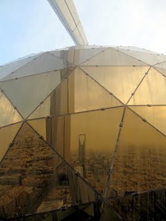
It was taken on top of Al Faisalyah Tower in Riyadh, Kingdom of Saudi Arabia. Kingdom Tower appears in the image center. Here, our sense of shape not only stems from the diffusely reflecting framework but foremost from reflections of the surrounding scene in the glass panels. For instance, the absence of any severe distortions indicates planarity of separate panels.
A technology called deflectometry, Shape from Distortion, or Shape from Specular Reflection imitates this behavior of a human observer. Basically, a camera images, via the specular surface, a sequence of patterns displayed on some form of active or passive screen.
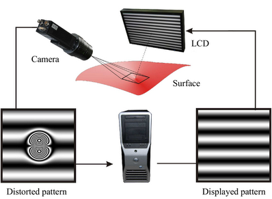
These patterns constitute an optical code, which allow for the assignment of each line of sight to the observed scene point. The recorded correspondences subsequently serve for the calculation of a 3D surface model. This reconstruction is plagued by an inherent ambiguity. An infinite number of surfaces lead to the same measurement. Consequently, a deflectometric algorithm requires some form of regularization, which in principle incorporates additional information to pick out a unique solution from the set of possible candidates.
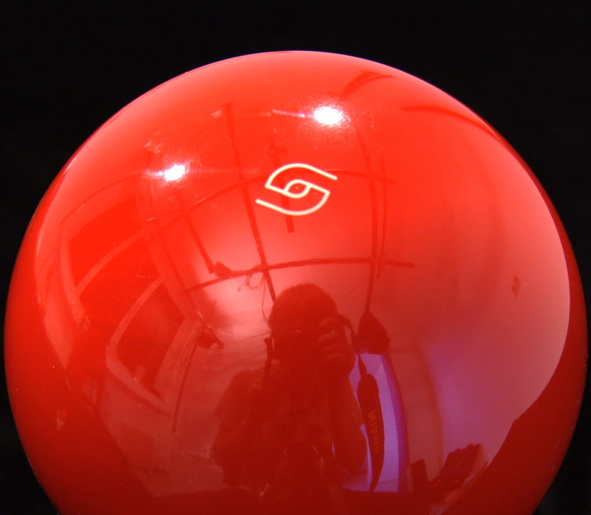
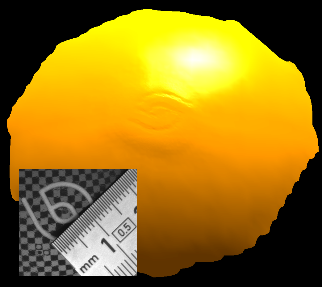
Below, an exemplary reconstruction result is shown. To attenuate details, the 3D model is superposed by the color-coded mean curvature distribution. The test object is a standard clear-coated bowling ball which has been deliberately damaged in the logo center. It is remarkable how submillimeter details such as peening mark and print are easily recovered by the deflectometry principle.
- Mirror surfaces behave like optical devices in the sightray path, particularly like a demagnifying glass if they are convex (with respect to the camera coordinate system). Inversely, the inspectable area becomes very small, even for reasonably large pattern generators. Consequently, objects of industrially relevant sizes require decomposing a deflectometric measurement into a (possibly extensive) series of imaging constellations.
- The information redundancy in overlaps between different measurement patches can be exploited for regularization in the above sense, namely to identify a unique candidate among the one-parameter family of possible solutions.
Datasets
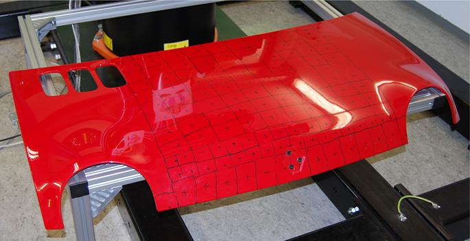
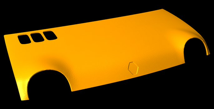
- Renault Twingo 93 model engine hood (265 views): For ground truth, a CAD model has been kindly supplied by the Renault company (not included in the download for reasons of copyright protection). Our polygonal approximation has an average resolution of about 8 mm. Nevertheless, higher sampling rates may be needed to reconstruct fine details such e.g. lacquering defects.
- [Download Part 1, .zip, 1.78 Gb]
- [Download Part 2, .zip, 1.83 Gb]
- [Download Part 3, .zip, 1.18 Gb]
- Bowling ball (15 views): This is the same object shown as an example above. Constructive constraints forbid deflectometric imaging of its entire surface. Thus, the data stems from a circular excerpt around the logo print. As strict tolerances apply to the production process of such sports equipment, it is straightforward to render ground truth from the diameter specified by the manufacturer to be 160 mm. [Download, .zip, 267 Mb]
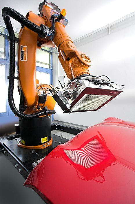
Data acquisition was performed by our compact robot-based sensorhead shown below, also see the attached video. We used the DLR toolbox for camera as well as hand-eye calibration. The local camera frames were calculated from the latter and joint position readings of the manipulator's internal sensors. All deflectometric images can be assumed calibrated with submillimeter accuracy. How to estimate the geometric relationship between camera and LCD will be subject of an upcoming publication.
There is one file for each separate view (with no. xxx) and two additional ones containing information on the involved imaging constellations:
- lxxx.vtk: vector-valued deflectometric image in VTK legacy format (see below). For each pixel, it contains the location of the observed scene point. All three coordinates are measured in millimeters and refer to the intrinsic camera coordinate system, not the world coordinate system.
- name_par.txt: To appeal to users acquainted with the Middlebury dataset, we provide the intrinsic and extrinsic camera parameters in the known way. The following is a verbatim quote from the Middlebury website: "There is one line for each image. The format for each line is: 'lxxx.vtk k11 k12 k13 k21 k22 k23 k31 k32 k33 r11 r12 r13 r21 r22 r23 r31 r32 r33 t1 t2 t3'. The projection matrix for that image is K*[R t]. The image origin is top-left, with x increasing horizontally, y vertically."
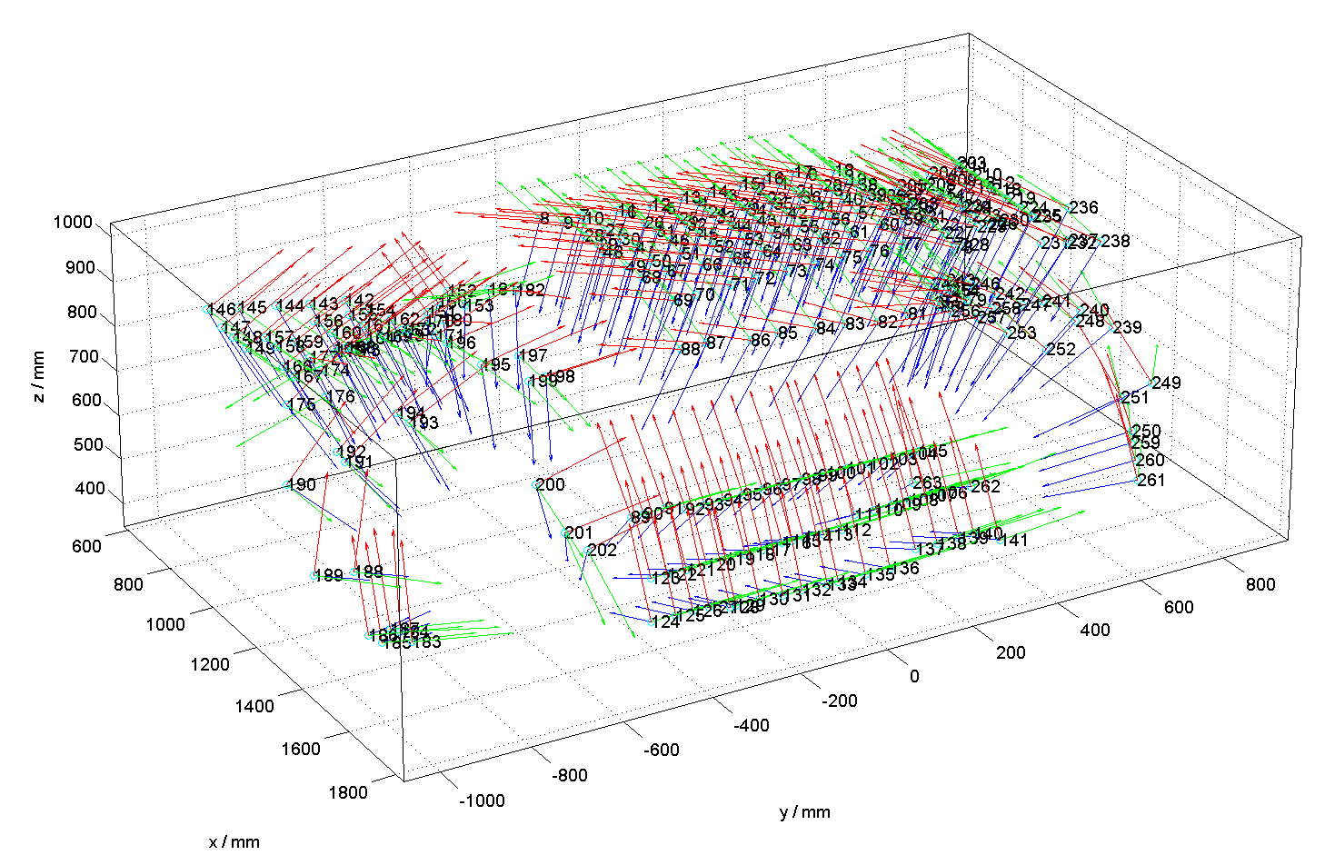
- name_views.fig: This MATLAB figure contains a visualization of all camera frames and might give an impression about the overall geometric situation, e.g. for initialization.
Submit Results
We currently only accept reconstructed models in form of a triangular manifold mesh in one of the following common formats:
- Wavefront 3d model (.obj)
- Standford Triangle Format (.ply)
- Stereolithography model (.stl)
- Legacy VTK format (.vtk)
If not excessively big, send your binary-encoded or compressed file to Jonathan Balzer via email. Altenatively, provide SSH, web, FTP access, or similar. Please, include run-time, processor type, and CPU speed obtained for each dataset.
Evaluation
No results received so far. We plan to adopt the evaluation methodology as described in Seitz et al. (see references below).
References
- J. Balzer, S. Höfer, and J. Beyerer,Multiview Specular Stereo Reconstruction of Large Mirror Surfaces, to appear in Proc. of CVPR, 2011.
- J. Balzer, S. Werling: Principles of Shape from Specular Reflection, Elsevier Measurement 43, 2010.
- I. Ihrke, K. Kutulakos, H. Lensch, M. Magnor, W. Heidrich: State of the art
in transparent and specular object reconstruction, STAR Proceedings of Eurographics, 2008. - S. Seitz, B. Curless, J. Diebel, D. Scharstein, R. Szeliski: A Comparison and Evaluation of Multi-View Stereo Reconstruction Algorithms, Proceedings of CVPR, 2006.
- S. Seitz et al.: Multi-view stereo evaluation web page.

